How Many Layers Does a Flexible Printed Circuit Board Typically Have?
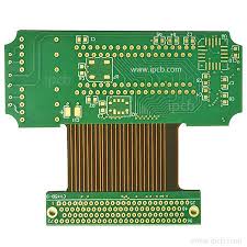
Flexible Printed Circuit Board
A flexible printed circuit board (FPC) has several layers and differs from a rigid PCB in that it is designed to bend and stretch. They are much lighter than rigid PCBs because they utilize a very thin substrate made of polyester or polyimide material–films that can be 12-120 microns thick. Conductive material traces are etched on these substrates in as many layers as the flex design requires. These layers are then laminated together and covered with a protective coverlay to keep them from moisture and dirt. Depending on the design, the coverlay can also provide protection from electrical interference and reduce the risk of delamination.
Most flexible printed circuit board have between three and 12 layers. This allows them to achieve high-density routing while maintaining a small footprint. They are ideal for electronic devices that need to bend and flex, and they are particularly effective in applications that require a high level of connectivity or additional shielding.
There are various types of flex circuits categorized by their level of flexibility, construction and materials, and the presence or absence of plated-through holes (PTH). Most flex circuits use copper foils as the conductive element because they offer an excellent balance between cost and physical and electrical performance. Copper foils can be used in a variety of ways, but the type of copper is crucial to a flex circuit’s lifespan. Electrodeposited copper is prone to work-hardening and fatigue that leads to breakage, so it’s important to use higher-grade rolled-annealed (RA) copper in a flex circuit for increased longevity.
How Many Layers Does a Flexible Printed Circuit Board Typically Have?
These copper layers are bonded to the flex base material or to the rigid PCB substrate in a rigid-flex circuit using epoxy. They are then insulated from each other and from corrosion using a coverlay, which is typically a flexible film such as PI or PET. The coverlay is a key part of the FPC’s thickness because it will be subjected to a lot of stress from bending, rolling and handling. It also protects the copper from contaminants such as solder paste during assembly and use.
An important issue in both flex and rigid-flex circuits is layer delamination, which occurs when the layers of the flex or rigid-flex circuit detach from one another, damaging the circuitry. This can be prevented by the careful selection of PCB materials, especially those that are capable of withstanding high temperatures and mechanical stresses.
For instance, FR4 and Kapton are often used as stiffeners to boost the bending resistance of a flex circuit and increase its life-span. They can be placed along the edges of a flex circuit or in specific flex zones to prevent delamination, as well as enhance its mechanical strength, weight balance and heat dissipation. Stiffeners can be positioned between the RA copper layers and PI or PET films to further protect them. For the best results, stiffeners should be sized to minimize their impact on signal integrity and avoid excessive strain in the circuit traces. In addition, the stiffeners should be bonded to the base material and copper using pressure-sensitive adhesives or acrylic thermally cured adhesives.